MADBUS
Work completed as part of the Robotics and Automation Summer School at Los Alamos National Laboratory. Worked on and written with Olyvia Hanken-Arlen, Anunth Ramaswami, Jessica Mendez, Colin Sanders, Matthew Hammond, and Dr. Beth Boadman. Supported by Los Alamos National Laboratory and approved for release under LA-UR-24-33374.
Abstract
In acting upon its mission of nuclear deterrence, the Y-12 National Security Complex produces material that poses a radiological hazard to those responsible for its containment, transport, and storage. Because of the nature of this hazard, material transportation between Y-12 and other facilities utilizes specialized shipping containers. An automated robotic bolting system was proposed in order to keep radiological exposure ALARA, as well as to allow workers to perform other tasks in conjunction with the bolting/unbolting process. An additional requirement was identified for the system to be mobile, as the shipping containers weigh up to 726 kg (1,600 lbs) and therefore are not practical to move to a stationary bolting system. Thus, the Robotics & Automation Summer School (RASS) at LANL was commissioned to produce a prototype of the system. The authors’ robotics-based response to this challenge is the “Mobile Automated DOE shipping container Bolting and Unbolting System”, or MADBUS.
The prototype described in this paper is contained on a custom-designed modular cart constructed from 38.1 mm (1.5in) 80/20 construction rail. The cart includes two semi-circular aligning plates with radii that correspond to the outer dimensions of the drum and CV, allowing the cart system to be wheeled flush with the containers for consistent manual alignment. On a basic level, the MADBUS bolting procedure operates as follows. Upon startup of the system with LabVIEW™,a, a lift initializes and raises a robotic arm to an appropriate height to reach the container bolts. The arm actuates and positions a magnetized nutrunner socket over a particular bolt in the cart’s bolt management module (BMM). The arm moves to accept a bolt head into its magnetized socket and unscrew the bolt from its holder. With a bolt held in the socket, a machine vision camera identifies empty bolt holes in the drum. The arm then positions the socket with bolt over the hole and descends the end effector into position. The nutrunner tightens the bolt to a specified torque. The arm moves back into position to retrieve the next bolt in the BMM, and the process repeats for the next bolt in the star-shaped bolting pattern. The outer drum bolt tightening requires two passes of increasing torque to get to its final specification. Conversely, the unbolting process starts with the camera identifying a bolt head in the container flange, which the nutrunner loosens. The freed bolt is lifted with the magnetic socket and screwed into its place in the BMM. This process repeats around the container.
The backbone of the MADBUS is a FANUC®,b CRX-20iA arm, communicating with an R-30iB Mini Plus control box. Bolts and bolt holes of interest are identified with a Cognex®,c Insight 2801 camera. Bolting action is executed by an Atlas Copco®,d ETD STR61-120-13 nutrunner, controlled by and programmed via an Atlas Copco® Power Focus 8. Both devices are attached to the end of the arm by a custom-machined aluminum bracket. An OnRobot®,e Lift100 allows the arm to be raised to a height appropriate for reaching either the outer drum, the shorter CV, or lowering fully for transport. Control of the Lift100 and Atlas Copco® nutrunner is via digital output from the FANUC® control box. Interface with the control box, and by extension the broader system, is via the DigiMetrix FANUC Library in LabVIEW™. The Human Machine Interface (HMI) is also within LabVIEW™, communicating with the total system via ethernet connection.
aLabVIEW™ is a trademark of National Instruments. bFANUC® is a registered trademark of FANUC CORPORATION in the United States and other countries. cCOGNEX® is a registered trademark of COGNEX CORPORATION in the United States and other countries. dAtlas Copco® is a registered trademark of ATLAS COPCO AKTIEBOLAG in the United States and other countries. eOnRobot® is a registered trademark of OnRobot A/S in the United States and other countries.
Introduction
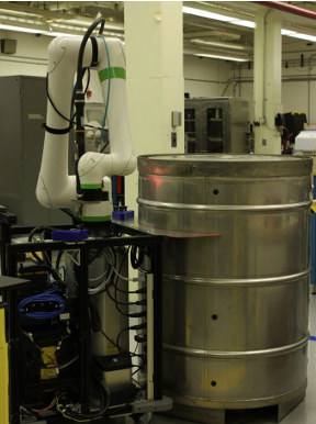
The transport of radiologically hazardous materials on public roads is necessary for furthering the nuclear deterrence missions of LANL, Y-12, and similar facilities. Annually, The United States Department of Energy (DOE) transports about 5,000 shipments including radioactive, hazardous, and non-hazardous materials (D.O.E., 2024). DOE has developed several unique shipping containers for such materials, which require particular bolting and unbolting procedures to ensure their reliability and to comply with inspection policies (N.R.C, 2021). These procedures, which include manually executing specific bolting patterns and torque specifications, have been identified to be time consuming and physically demanding for workers (Sakalaukus et al., 2019). The Mobile Automated DOE shipping container Bolting and Unbolting System (MADBUS), Figure 1, was developed at LANL in order to lessen physical and radiological stress for its users. A robotic solution to this challenge was thought to be ideal, as object identification and torquing both had existing precedents in the robotics industry, even for DOE shipping containers (Hammond et al., 2024). However, the challenge presented by this iteration was to create a mobile system that could be operated autonomously from a distance and could be adapted for DOE containers of any dimension.
System Requirements
The MADBUS system must
- Be contained in a mobile cart that can lock in place for bolting/unbolting.
- Remove a bolt from a circular shipping container for disassembly.
- Store removed bolts in a convenient location for later use.
- Retrieve bolts from storage for reassembly.
- Fasten bolts in two torque passes.
- Be adaptable to containers of varying heights and diameters.
Description
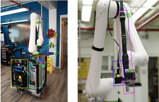
The MADBUS, Figure 2, features an arm (red), lift (light blue), control boxes (yellow), nutrunner (purple), and camera (dark blue) all packaged into a mobile cart. The cart features wheels that can swivel in any direction and can lock in place for stability during the bolting and unbolting process. This allows the entire platform to move and lock in place satisfying the first requirement. To bolt and unbolt a container, the system is first brought and aligned with the container using a series of drum aligners (green). Then, the system leverages a camera and computer vision capabilities to identify bolts or threaded holes. To actually tighten or loosen bolts, the system features an electric nutrunner. This allows the cart to satisfy the second, fourth, and fifth requirements.
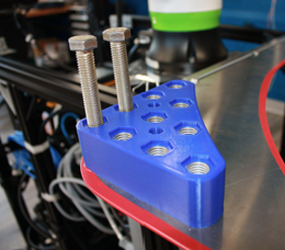
To store bolts that have been removed from the container, the system features bolt management modules (BMMs), Figure 3, with threaded holes that removed bolts can be torqued into for later use (e.g. for container assembly). This satisfies the third requirement. These BMMs are also easily detachable (fastened with 2 bolts) so that after a container has been disassembled, the BMMs can be taken off the MADBUS system. The MADBUS system can now be used to disassemble another container. When a container needs to be reassembled, the BMMs for that container can then be reattached. This allows the MADBUS system to assemble and disassemble containers quickly and keep bolts removed from containers organized
Finally, in order to tackle containers of different heights, the MADBUS system features a robotic lift. This allows the arm to be raised and lowered to different heights for different containers. This satisfies the sixth requirement.
Hardware Elements
| Hardware Element | Traditional Use |
|---|---|
| FANUC® CRX-20iA/L Cobot | Collaborative 6-DOF robotic arm (20 kg payload) |
| FANUC® R-30iB Mini Plus Controller | Controller for FANUC® collaborative arms |
| OnRobot® Lift100 Robot Elevator | Robot elevator for palletizing tasks |
| Omnidirectional Pushcart | Manual translation and locking of MADBUS |
| OnRobot® Compute Box | Configures and transmits data to OnRobot devices |
| Cognex® In-Sight 2801 Camera | Machine vision camera with pre-trained neural nets |
| Atlas Copco® ETD STR61-120-13 Nutrunner | Electric assembly tool for tightening/loosening bolts |
| Atlas Copco® Power Focus 8 Torque Controller | Controller for Atlas Copco® tightening tools |
| NETGEAR®,f 8-port Gigabit Ethernet Switch | Manages Ethernet communication among devices |
fNETGEAR® is a registered trademark of NETGEAR, INC. in the United States and other countries.
Software Elements
| Software Element | Traditional Use |
|---|---|
| LabVIEW™ | Graphical programming for hardware control |
| DigiMetrix FANUC Library | LabVIEW™ library for FANUC® robot control |
| Cognex® In-Sight Vision Suite | Configure and communicate with Cognex® cameras |
| FANUC® PAC R785 Ethernet/IP Scanner | Ethernet/IP scanning for FANUC® R-30iB |
| FANUC® PAC R632 KAREL | Programming language for FANUC® R-30iB |
| FANUC® PAC R648 User Socket | Socket messaging for FANUC® R-30iB |
| SolidWorks®,g | CAD and simulation for 3D parts |
g SolidWorks® is a registered trademark of Dassault Systèmes SolidWorks Corporation in the United States and overseas.
MADBUS Operation
The MADBUS performs assembly and disassembly procedures for DOE shipping containers.Course alignment witha container is first provided by the operator utilizing the cart to fix the system at a known distance from the center of the container via the cart’s container alignment tools. Figure 1 depicts the cart in this state. Upon locking the cart’s wheels to fix the system in place, a LabVIEW™ program is run corresponding to either a bolting or unbolting procedure.
Automated Assembly
In the assembly procedure, bolts are already stored in the cart’s BMMs. The arm with nutrunner attachment moves to saved coordinates above one of these bolts and activates a loosening sequence. Initially, the nutrunner slowly spins as the arm lowers onto the bolt. This allows the nutrunner’s socket to catch the bolt. Then, the nutrunner initiates a faster spin and the arm raises upward, capturing the bolt. With the bolt stored in the nutrunner’s magnetic socket, the arm shifts to a position above the perimeter of the container. If the container is tall, the system may need to engage its lift to allow the arm to reach over the container. The machine vision camera then scans for the presence of a bolt hole. If no such target is detected, the arm moves along the perimeter of the container, with the camera taking snapshots at intervals defined by the container’s bolt pattern radius and number of bolts, until such a target is found.
Upon detecting a hole, the arm aligns its nutrunner over the bolt and a tightening sequence is activated. Initially, a slow spin is initiated as the nutrunner is lowered onto the hole. This allows the bolt’s threads to engage with the bolt hole. With the threads engaged, the nutrunner initiates a faster spin until the bolt is tightened to an initial torque. This process repeats until every bolt is tightened to the correct initial torque. The system then tightens every bolt to their final torque in a second pass, as outlined in Figure 4.

Automated Disassembly
The disassembly procedure is essentially the inverse of the assembly case. All of the bolts start on the container. The arm and nutrunner move over the container and search for a bolt along the perimeter of the container. Once found, the nutrunner initiates a loosening sequence and the bolt is extracted from the container. The arm then transports the bolt to a BMM and tightens it into the corresponding hole. This process is repeated for every bolt on the container.
Bolt/Hole Detection
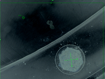
The core of this system is the bolt/hole alignment procedure. This begins with using the Cognex® camera to detect bolts and holes. To detect these features, the Cognex® camera features a pre-trained neural network for feature detection. This network can be tuned using the Cognex® Vision Suite by providing training examples of bolts and holes. The Cognex® Vision Suite also allows filters to be overlaid onto camera images. An optical density filter was chosen as it helped make darker colored bolts stand out in comparison to the reflective containers.
Figure 5 illustrates an image taken by the camera with an optical density filter. As reflected by the image, the optical density filter makes the bolt pop out of the image and is easily identifiable by the camera. The green cross represents the center pixel coordinates of the bolt detected by the neural network.
Bolt/Hole Alignment
Upon identifying a target, we begin in the left image of Figure 6. The vision system is programmed to store the pixel coordinates (marked by the green cross in Figure 5) and transmit these coordinates to a LabVIEW™ program via a Telnet server. One challenge is that with a single camera, the real-world coordinates of a bolt are unobservable. However, given the known width of the bolts and the height of the container the bolts are sitting on (this gives us the depth of the bolts $z_t$), we can compute the real-world coordinates of the bolt using a scaling factor. This approach works well as the camera has already been distortion corrected using the camera matrix. Given pixel coordinates in the camera frame (red frame in Figure 6) $\left[x_{pc}, y_{pc}\right]^T$ we can calculate real world coordinates in the camera frame $\left[x_{rc}, y_{rc}\right]^T$ ($z_{rc}$ is already known) as shown below.
\[\alpha = \frac{\text{Object Width}}{\text{Pixel Width}}\] \[\begin{bmatrix}x_{rc}\\y_{rc}\end{bmatrix} = \alpha \begin{bmatrix}x_{pc}\\y_{pc}\end{bmatrix}\]However, arm position movements are supplied using the black global frame also shown in Figure 6. To shift between these frames, we simply multiply by a 2D rotation matrix ($R_{uc}$) as shown below.
\[\begin{bmatrix}x_{ru}\\y_{ru}\end{bmatrix} = R_{uc} \begin{bmatrix}x_{rc}\\y_{rc}\end{bmatrix} ,\quad z_{ru} = z_{rc}\]Using these real-world coordinates in the universal frame, we can move the arm by $\left[x_{ru}, y_{ru}\right]^T$ to align the bolt with the center of the camera. This alignment process is performed twice to ensure the bolt is centered with the camera, Figure 6 middle image.
Once the bolt has been aligned with the camera, the nutrunner is a fixed offset from the center of the camera in the camera frame. Using a very similar process to that outlined above, this offset can be transformed into the black global frame and the bolt can be aligned with the nutrunner as shown in the right image of Figure 6.

Control of Atlas Copco® Nutrunner
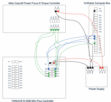
Another essential component of automated bolting and unbolting is the tightening and loosening cycle. The nutrunner control box touchscreen interface can be used to construct the necessary sequences. When activated, these procedures can be used to run the nutrunner at specific speed and torque profiles optimized for tightening and loosening bolts. First, individual Tightening Programs specify a specific torque, direction, and termination condition for a given step in the overall bolting or unbolting process. Subsequently, each program step is compiled into a batch sequence, which strings the independent programs together in their desired order of implementation. Execution of these programs is triggered via the control box’s digital I/O pins, as discussed in the Digital I/O Section.
Control of OnRobot® Lift
The lift allows the base of the arm to be raised to different heights in order to bolt and unbolt different height containers. The lift is paired with a compute box in which the specific lifting programs are stored. Lift programs are written via the OnRobot® proprietary webclient and correspond to particular movement or initialization commands. Each individual program can be activated via its own designated compute box digital I/O pin, as specified in the Digital I/O Section.
Ethernet Communication
Ethernet communication is essential to MADBUS, as it connects the robotic arm controller, compute box, and machine vision camera with the LabVIEW™ and Cognex® Vision Suite softwares on the operator’s computer. All ethernet communication is handled by LabVIEW™ scripts using TCP/IP protocol. Communication with the machine vision camera is achieved via a Telnet server sending Cognex® Native Mode Commands.
Digital I/O
The FANUC® controller’s digital output board is utilized to send signals to both the nutrunner’s torque controller and the lift’s compute box, each of which have a dedicated digital input board. Concerted operation of the lift and nutrunner rely on digital I/O signals from the FANUC®, executed from the LabVIEW™ code. Further details on their operation can be found in the Control of Atlas Copco® Nutrunner Section and Control of OnRobot® Lift Section, respectively. A basic I/O wiring diagram for the MADBUS system is provided in Figure 7.
Discussion
This paper proposes and implements a mobile bolting and unbolting station for hazardous material shipping containers. By interfacing a robotic arm, lift, nutrunner, and camera over TCP/IP and ethernet communication using LabVIEW™, the initial system requirements were satisfied. To demonstrate these capabilities, the MADBUS was tested on a training DOE shipping container. A LabVIEW™ program was constructed that raises the lift so that the arm can reach over a tall training container. The arm then autonomously locates a bolt on a mock shipping container and unbolts it. It then stores that bolt into the BMM. A program was also written that removes a bolt from the BMM and tightens it to the mock container using two separate passes. This successfully demonstrates every capability of our system.
Future Work
The work done on this project was completed within a strict ten-week time constraint due to the timeline of the RASS program. The following suggestions for future work on this project would serve to improvethe ease of use and utility of the system beyond the scope of a ten-week program
- A motorized cart would allow the system to move under its own power, affording its use to operators with a wider range of abilities.
- The addition of an Atlas Copco® Socket Selector would enable the MADBUS to independently switch out its socket type when necessary (i.e. transitioning between different bolt head sizes for an inner and outer container), further reducing hands-on operator interference.
- The integration of a higher weight capacity robotic arm could enable the system to assist in the lifting and lowering of container components (i.e. container lids and inner vessels).
- Training of the machine vision program to identify visual damage to the containers or improper fastening hardware would give the system additional use cases for quality assurance.
- An upgraded end effector would allow for the handling of DOE shipping containers that utilize washers.
- A redesign of the bolt storage system could allow for more modularity via a quick-release mechanism. Additionally, a tracking mechanism could be incorporated to ensure containers remain paired with their dedicated fastening hardware.
- The torque controller’s software could be further utilized to generate a database of torque measurements for all containers.
- Further testing on a wider variety of DOE shipping containers would affirm the universality of the MADBUS.
Conclusion
The Y-12 National Security Complex identified a necessity for less manual interaction with DOE shipping containers, often containing radioactive materials, during their assembly and disassembly procedures. In response to this need, the MADBUS integrated many disparate components within LabVIEW™ in order to create an autonomous robotic bolting and unbolting system that could be executed and supervised from a distance. The system demonstrated its ability to recognize a bolt head or hole, position its nutrunner end effector over said target, and torque or loosen to particular specifications consistently and with little operator interference. Additionally, the mechanical design of the system was such that the entire unit was able to be maneuvered to a new drum by a single operator with a reasonable exertion of effort. According to each criteria set forth by the developers, the MADBUS successfully demonstrated its worthiness as a proof-of concept prototype for a mobile, remotely executed bolting/unbolting system for DOE shipping containers.
Acknowledgements
The work presented in this paper was supported by Los Alamos National Laboratory and is approved for release under LA-UR-24-33374.
This work was performed as a part of the Los Alamos National Laboratory’s Robotics and Automation Summer School led by Dr. Beth Boardman (Program Leader), Matthew Hammond (Deputy Program Leader), and Jessica Mendez (Technical Coordinator).
We thank all the staff of E-3 for their dedication to helping us succeed in our endeavors. Special thanks to Jessica Mendez and Colin Sanders for their time, mentorship, and guidance during this project.
We are grateful for Robert Natzic and Nicholas White for their part in realizing our physical designs.
References
2024
- Packaging and Transportation2024
- TAuRUS: Tool for Automated Robotic Unbolting and Safety2024
2021
- General standards for all packages2021
2019
- DESIGN OF THE DEFENSE PROGRAMS PACKAGE 3 (DPP-3)2019